

Application Notes for Microwave Attenuators
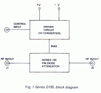
The Series D195 voltage-controlled linearized attenuator/modulators are integrated assemblies consisting of a Series 195 unit and a hybridized driver circuit which provides a nominal transfer function of 10 dB per volt. (See figure 1 below.)

All of the Series D195 units except the D1950A* exhibit fall times of 20 ns max and rise times of 1.5 µsec max for attenuation steps of 10 dB or more. For smaller excursions, the fall times can increase to several hundred ns, while the rise times remain essentially unchanged. In applications where a rapid return to insertion loss from any level of attenuation is required, Option 59 is available. With this option, an external pulse is applied to trigger a high-speed reset circuit, and recovery times of 200 ns max are obtained. Where use of an external reset pulse as described above is not feasible, an internal reset option (Option 58) is available which will automatically reset the unit to insertion loss within 200 ns for a step of 50 dB or more. The fall and rise time specifications for the D1950A* are 500 ns max and 10 µsec max, respectively. Options 58 and 59 are not available for this model.
*Model D1950A is a special-order product. Consult factory before ordering.
- Absorptive
- Linearized
- Frequency range: 0.5 to 18 GHz
- High performance MIC quadrature hybrid design
- High speed
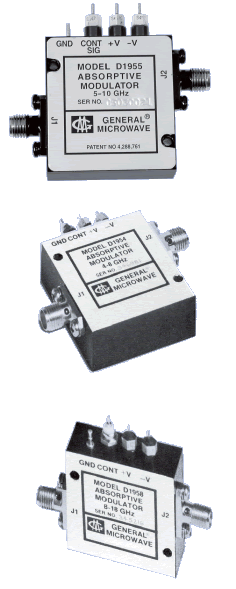
IN THIS SERIES
ARE EQUIPPED
WITH INTEGRATED DRIVERS
| MODEL | FREQUENCY RANGE (GHz) |
MAX. INSERTION LOSS (dB) |
MAX. VSWR | MAX. FLATNESS (±dB) AT MEAN ATTENUATION LEVELS UP TO |
||||
| 10 dB | 20 dB | 40 dB | 60 dB | 80 dB | ||||
| D1950A* | 0.5 – 1.0 | 1.5 | 2.0 | 0.3 | 0.8 | 1.7 | 3.0 | 3.6 |
| D1951 | 1.0 – 2.0 | 1.7 | 1.5 | 0.3 | 0.8 | 1.5 | 1.6 | |
| 0.75 – 2.25(1) | 1.8 | 2.0 | 0.5 | 1.4 | 3.0 | 3.5 | ||
| D1952 | 2.0 – 4.0 | 2.0 | 1.5 | 0.3 | 0.8 | 1.5 | 1.6 | |
| 1.5 – 4.5(1) | 2.1 | 2.0 | 0.5 | 1.4 | 3.0 | 3.5 | ||
| D1953 | 2.6 – 5.2 | 2.2 | 1.6 | 0.3 | 0.8 | 1.5 | 1.8 | |
| 1.95 – 5.85(1) | 2.3 | 2.1 | 0.5 | 1.4 | 3.0 | 3.5 | ||
| D1954 | 4.0 – 8.0 | 2.6 | 1.7 | 0.3 | 0.8 | 1.5 | 1.6 | |
| 3.0 – 9.0(1) | 2.7 | 2.2 | 0.5 | 1.4 | 3.0 | 3.5 | ||
| D1955 | 5.0 – 10.0 | 2.8 | 1.7 | 0.5 | 0.9 | 1.5 | 1.6 | |
| 3.75 – 11.25(1) | 2.9 | 2.2 | 0.7 | 1.4 | 3.0 | 3.5 | ||
| D1956 | 6.0 – 12.0 | 2.9 | 1.8 | 0.7 | 1.0 | 1.5 | 1.6 | |
| 4.5 – 13.5(1) | 3.0 | 2.2 | 0.9 | 1.5 | 3.0 | 3.5 | ||
| D1958 | 8.0 – 18.0 | 3.0(2) | 1.8(2) | 0.7 | 1.0 | 1.5 | 1.6 | |
| 6.0 – 18.0(1) | 3.0(2) | 1.8(2) | 0.9 | 1.5 | 3.0 | 3.5 | ||
*Model D1950A is a special-order product. Consult factory before ordering.
(1) Specifications for the extended frequency ranges are typical.
(2) Except from 16 – 18 GHz where insertion loss is 4.0 dB max and VSWR is 2.0 max.
PERFORMANCE CHARACTERISTICS
|
|
||||||||||||||||||||||||||||||||||||||||||||||||||||||||||||||||||||||
*Model D1950A is a special-order product. Consult factory before ordering.
|
|
|||||||||||||||||||||||||||||||||||||||
(1) Where use of an Option 59 external reset pulse (see note 2 below) is not feasible, this option is available which will
automatically sense the slope and magnitude of the control signal and reset the unit to the insertion loss state within
200 ns for a stop of 50 dB or more.
(2) An external terminal is provided for the user to apply a fast (10 ns, max rise time) positive-going 3-volt pulse at
least 0.5 µsec wide to accelerate the return of the attenuator to the insertion loss state with the simultaneous
lowering of the control signal to the zero voltage level. This reset can be accomplished within 200 ns.
(3) The input impedance of units equipped with Option 59 is a circuit equivalent to approximately 50 pF in series with a
parallel combination of 100 pF and 1000 ohms.
DIMENSIONS AND WEIGHTS
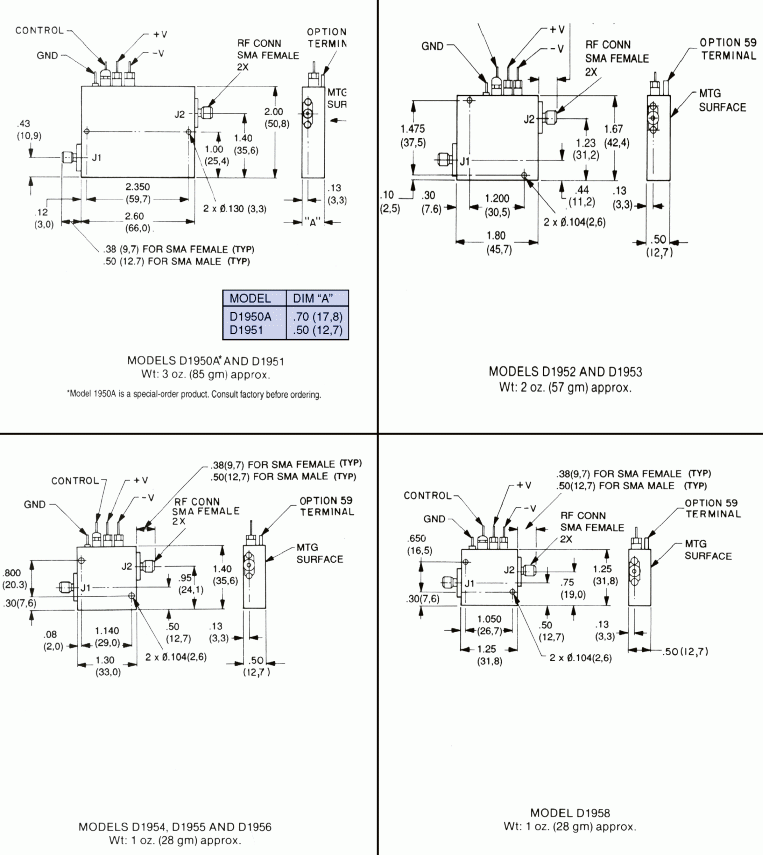
Dimensions are stated in inches (mm). Tolerances,
unless otherwise indicated: .XX ±.02; .XXX ±.008