

Application Notes for Microwave Attenuators
The 346C Series is a family of Non-reflective PIN diode attenuators, each programmable to 60 dB in attenuation steps as low as 0.06 dB, and covering the frequency range from 0.5 GHz to 18 GHz in four overlapping multi-octave bands.
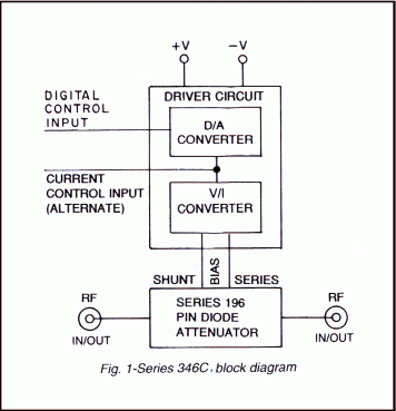
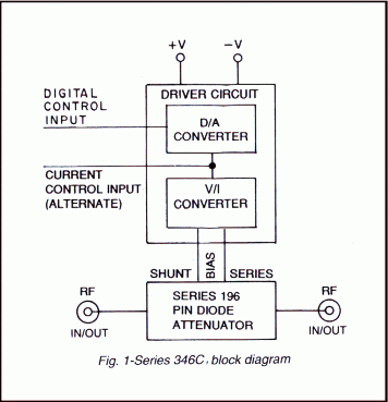
Each model in the Series comprises of an integrated assembly of a dual (current-controlled) PIN diode attenuator, and a driver circuit consisting of a D/A converter and a voltage-to-current converter. (See Figure 1 below)
The RF circuit consists of two wide-band, T-pad attenuator sections in tandem. The levels of series and shunt currents required to maintain a bilateral match at all attenuation levels are provided by the driver.
This arrangement assures monotonicity over the operating band at all levels of attenuation and for any programmed attenuation step.
- Frequency range: 0.5 GHz-18GHz in four overlapping ranges
- Attenuation range: 60 dB
- Programming: 10-Bit binary
- LSB: 0.06 dB
- Monotonicity: guaranteed
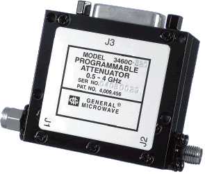 Fig. 2 – 3460C
PERFORMANCE CHARACTERISTICS
| CHARACTERISTIC | MODEL 3460C* |
MODEL 3461C |
MODEL 3462C* |
MODEL 3468C |
| Frequency Range (GHz) | 0.5-4 | 0.5-8 | 2-8 | 2-18 |
| Mean Attenuation Range (dB) | 60 | 60 | 60 | 60 |
| Insertion Loss (dB) (max) | 2.5 | 2.5 (0.5-4 GHz) 3.2 (4-8 GHz) |
3.2 | 4.5 |
| VSWR (max) | 1.8 | 1.8 | 1.8 | 2.0 |
| Flatness up to 20 dB 40 dB 60 dB |
± 0.5 dB |
± 0.75 dB |
± 0.75 dB |
± 1.0 dB |
*Special-order product. Consult factory before ordering.
|
|
|||||||||||||||||||||||||||||||||
|
|
||||||||||||||||||||||||||||||||||||||||||||||||||||||||||||||||||||||||
NOTES
(1) All unused logic inputs must be grounded.
(2) For normal programming control Pin 1 must be grounded or at logic “0” . Application of logic “1” to Pin 1 overrides the digital input and sets the unit to Insertion loss. For units with complementary programming (Option 2), the application of a logic “1” to Pin 1 sets the unit to high isolation (60 dB or greater).
(3) Pin 2 is available to (a) monitor the D/A converter output, (b) apply a modulation signal from a current source, or (c) apply an independent analog signal for turn-on, turn-off or vernier attenuation levels. If not used as described in (a), (b) or (c). Pin 2 must be open.
(4) The Series 346C attenuators are 10-bit digital attenuators. In order to use this device with a lesser number of bits (lower resolution), the user may simply ground the logic pins for the lowest order unused bits. For example, a Series 346C unit operated as an 8-bit unit would have Pin 15 and Pin 3 connected to ground. All other parameters remain unchanged.