

Application Notes for Microwave Attenuators
SERIES 195
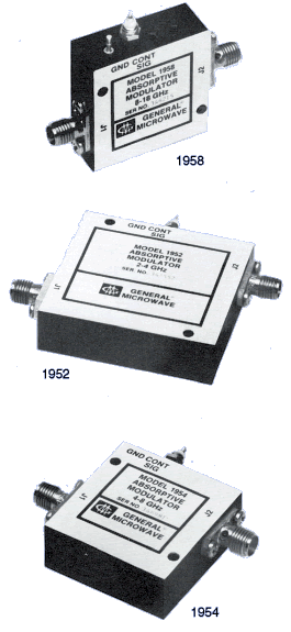
Series 195 current-controlled attenuator/modulators provide small size with greater than octave-bandwidth performance at low cost. All models except the 1950A* provide a minimum of 60 dB of attenuation with fall times of 20 ns max, and rise times ranging from 25 ns for the 1951 and 1952 to 125 ns max for the 1956 and 1958. The 1950A* provides a minimum of 80 dB of attenuation with a fall time of 50 ns max and a rise time of 250 ns max. These characteristics make this series suitable for a wide range of applications including level setting, complex amplitude modulation, pulse modulation and high-speed switching. The eight models in the Series 195 encompass a frequency range from 0.5 to 18 GHz. All models except the 1950A* are capable of extended bandwidth operation, typically 3:1, with only moderate degradation in performance at the band edges.
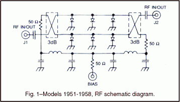
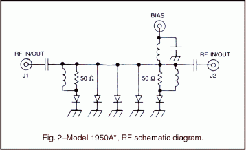
As shown in figures 1 and 2 below, the RF circuit employed in all models except the Model 1950A* uses two shunt arrays of PIN diodes and two quadrature hybrid couplers. The quadrature hybrids are of a unique GMC microstrip design which are integrated with the diode arrays to yield a minimal package size. The RF circuit employed in the Model 1950A* uses one shunt array of PIN diodes with input and output impedance matching circuits.
*Model 1950A is a special-order product. Consult factory before ordering.
- Absorptive
- Current controlled
- 0.5 to 18 GHz frequency range
- High performance MIC quadrature hybrid design
- High speed
| MODEL | FREQUENCY RANGE (GHz) | MAX. INSERTION LOSS | MAX. VSWR | MAX. FLATNESS (± dB) AT MEAN ATTENUATION LEVELS UP TO |
||||
|---|---|---|---|---|---|---|---|---|
| 10 dB | 20 dB | 40 dB | 60 dB | 80 dB | ||||
| 1950A* | 0.5 – 1.0 | 1.4 | 2.0 | 0.3 | 0.8 | 1.7 | 2.2 | 3.2 |
| 1951 | 1.0 – 2.0 | 1.3 | 1.5 | 0.3 | 0.8 | 1.5 | 1.6 | |
| 0.75 – 2.25(1) | 1.4 | 2.0 | 0.5 | 1.4 | 3.0 | 3.5 | ||
| 1952 | 2.0 – 4.0 | 1.5 | 1.5 | 0.3 | 0.8 | 1.5 | 1.6 | |
| 1.5 – 4.5(1) | 1.6 | 2.0 | 0.5 | 1.4 | 3.0 | 3.5 | ||
| 1953 | 2.6 – 5.2 | 1.7 | 1.6 | 0.3 | 0.8 | 1.5 | 1.6 | |
| 1.95 – 5.85(1) | 1.8 | 2.1 | 0.5 | 1.4 | 3.0 | 3.5 | ||
| 1954 | 4.0 – 8.0 | 2.0 | 1.7 | 0.3 | 0.8 | 1.5 | 1.6 | |
| 3.0 – 9.0(1) | 2.1 | 2.2 | 0.5 | 1.4 | 3.0 | 3.5 | ||
| 1955 | 5.0 – 10.0 | 2.2 | 1.7 | 0.5 | 0.9 | 1.5 | 1.6 | |
| 3.75 – 11.25(1) | 2.3 | 2.2 | 0.7 | 1.4 | 3.0 | 3.5 | ||
| 1956 | 6.0 – 12.0 | 2.3 | 1.8 | 0.7 | 1.0 | 1.5 | 1.6 | |
| 4.5 – 13.5(1) | 2.4 | 2.2 | 0.9 | 1.5 | 3.0 | 3.5 | ||
| 1958 | 8.0 – 18.0 | 2.5(2) | 1.8(2) | 0.7 | 1.0 | 1.5 | 1.6 | |
| 6.0 – 18.0(1) | 2.5(2) | 1.8(2) | 0.9 | 1.5 | 3.0 | 3.5 | ||
NOTES
(1) Specifications for the extended frequency ranges are typical.
(2) Except from 16-18 GHz where Insertion loss is 3.5 dB max and VSWR is 2.0 max.
*Model 1950A is a special-order product. Consult factory before ordering.
PERFORMANCE CHARACTERISTICS
|
|
||||||||||||||||||||||||||||||||
*Model 1950A is a special-order product. Consult factory before ordering.
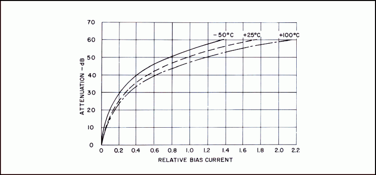
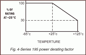
|
|
||||||||||||||||||||||||||||||||
DIMENSIONS AND WEIGHTS
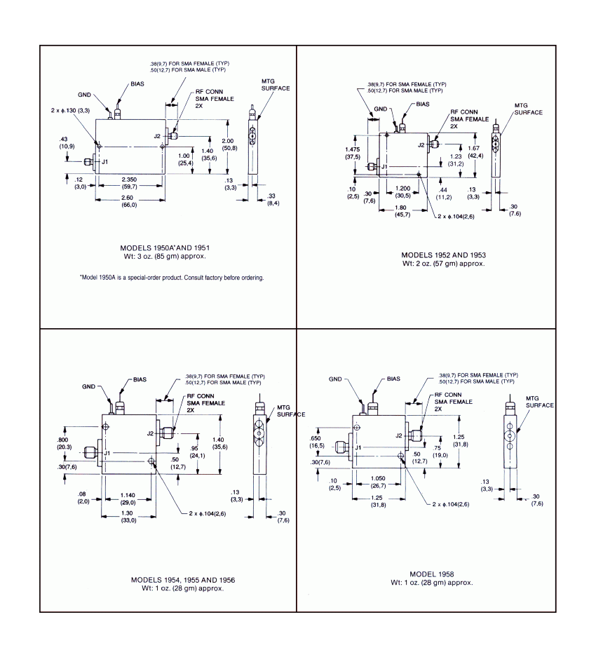
Dimensions are stated in inches (mm). Tolerances,
unless otherwise indicated: .XX ±.02; .XXX ±.008