Need a Custom Microwave Solution?
Get in touch with our engineering team for a tailored quote.
Contact Us

Request More Product Info | Limiters Selection Guide
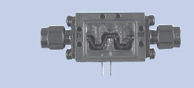
Kratos General Microwave offers PIN diode-based limiters, supporting up to 600 watts of pulsed power.
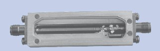
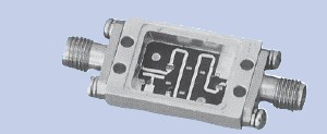
The limiters can be supplied in various configurations: connectorized, drop-in or with field-removable connectors.
The limiters can be supplied as stand alone limiters, or as integrated modules that include the limiter and a control component such as a switch or attenuator as specified in the following:
SWITCH LIMITERS
A switch module is available in front or after the limiter, handling up to 25-watt CW/ 250-watt Peak power.
LIMITER ATTENUATOR
Provides combined protection and attenuation capabilities (Option).
LIMITER AMPLIFIER
A limiter and an amplifier module that maintains the required power. Signal is amplified if power is not within the specified range (Option).
LOW POWER LIMITERS
Support 1GHz – 18GHz, up to 20-Watts Average power and 500-watt Peak power.
HIGH POWER LIMITERS
Support 1GHz – 12GHz, up to 60-Watts Average power and 400-watt Peak power.
PARAMETERS TRADE-OFF
The main parameters of Limiter specifications are Frequency Band, Input Power and Flat Leakage. Note that there is a trade-off between these parameters.
|
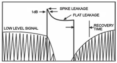
DEFINITION OF PARAMETERS Recovery Time: The time period from the end of a high power pulse to the point where the insertion loss value has returned to within 3 dB of the quiescent loss state. Spike Leakage: After pulsed high power is applied, the limiter will momentarily pass significantly more power than when it is totally saturated. This power rise is seen as a spike on the leading edge of the leakage pulse. The rise time of the high power pulse and the turn-on time of the diode determine the spike’s amplitude. The spike is defined by its energy content, i.e., in ergs. The formula for calculating the spike leakage is as follows: SPIKE LEAKAGE (ERGS) = ts x Psx 107 where ts equals spike width at the half-power point in seconds, and Ps equals maximum spike amplitude in watts.
Power Handling: There are two important things to consider when defining the power handling required of a limiter. Two important considerations for defining the required power handling of a limiter are:
|
|
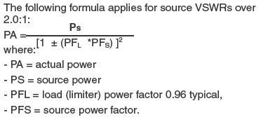
Any mismatch at the source reflects power back toward the limiter, resulting in standing waves. In a correct limiter-source phase relationship, the maximum current point occurs at the input diode, causing the diode to dissipate a greater level of power than incident power. For a source VSWR of up to 2.0:1, an approximate maximum effective power can be achieved by multiplying the source VSWR by the incident power.
CONSIDERATIONS IN USING LIMITERS
CAUTION! Limiters are NOT bilateral components! They have a defined input and output. Backwards installation will damage the component. |
| Operating Temperature Range……………………………
|
–55°C to +85°C |
|
Non-Operating |
–55°C to +85°C |
| Humidity……………………….. | RTCA/DO-160D, Category B Sec. 6.3.2). RH Operating 95% @ 60 oC |
| Shock…………………………… | RTCA/DO-160D Section 7 Category B |
| Vibration………………………. | RTCV/DO-160D Category R or R2 Sec conde,) Section 8, Par. 8.7.2 Fig. 8-1 & 8-4. Curve C & C1, G rms 4.12 & 5.83. Random 30 min at performance level and 3 Hrs at endurance level for each axis. |
| Altitude………………………….. | (70,000 ft.) |
| Temp. Cycling……………….. | MIL-STD-202F, Method 107D, Cond. A, 5 cycles |
The information contained in this data sheet is basic marketing information and does not contain any export controlled information.
Get in touch with our engineering team for a tailored quote.
Contact Us