

pplication Notes for RF Switches
MODELS 9140-500 and 9240-500
These switches provide high-performance characteristics over a multi-octave frequency range. Model 9140-500 covers the 1 to 18 GHz frequency range while the Model 9240-500 covers the 0.2 to 4 GHz range. Their description and operation are the same as that for the Models 9120-500 and 9220-500 SP2T switches.
MODELS 9140T-500, 9140W-500 and 9240T-500
These switches are Non-reflective versions of the switches described above.
MODELS 9140AH-500 and 9140AHT-500
These switches are the same as the 9120AH-500 and the 9120AHT-500 except for the number of ports.
SERIES F91 and F92
The Series F91 and F92 switches are the same as the corresponding Series 91 and 92 models except the units are equipped with integrated drivers.
SERIES G91 and G92
Operating from +5 and +15V power supplies only, the G-series switches provide high performance characteristics at relatively high speeds over multi-octave frequency ranges. The series includes low Insertion loss and high isolation models in both reflective and non-reflective configurations. Series G91 units cover the frequency range of 1 to 18 GHz; Series G92 units cover the frequency range of 0.2 to 4 GHz. The design is based on an integrated circuit assembly of PIN diodes mounted in a microstrip transmission line as shown below. The currents required to switch the ports ON or OFF are provided by the integrated driver, which is controlled by external TTL logic signals.
- Frequency range (Series 91):
1 to 18 GHz - Frequency range (Series 92):
0.2 to 4 GHz - Rise and fall times as fast as
10 ns - Reflective and Non-reflective models
- Low VSWR and Insertion loss
- Isolation: up to 60 dB
- Miniature size, light weight
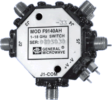
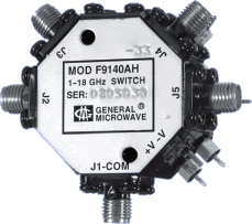
(With INTEGRATED Driver)
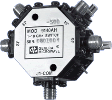
(DRIVERLESS)
| MODEL NO.(1) | CHARACTERISTIC | FREQUENCY (GHz) | |||||
| 0.2-1 | 1-2 | 2-4 | 4-8 | 8-12.4 | 12.4-18 | ||
| 9140-500 F9140 |
Min. Isolation (dB) Max. Insertion Loss (dB) Max. VSWR (ON) |
– – – |
60 1.4 1.75 |
60 1.4 1.75 |
60 1.5 1.75 |
60 2.0 1.75 |
50 2.8 2.0 |
| G9140* |
Min. Isolation (dB) Max. Insertion Loss (dB) Max. VSWR (ON) |
– – – |
60 2.0 1.5 |
60 2.0 1.5 |
60 2.2 1.7 |
60 2.7 1.7 |
50 3.0 2.0 |
| 9240-500* F9240* |
Min. Isolation (dB) Max. Insertion Loss (dB) Max. VSWR (ON) |
60 1.5 1.6 |
60 1.5 1.6 |
60 1.5 1.6 |
– – – |
– – – |
– – – |
| G9240* | Min. Isolation (dB) Max. Insertion Loss (dB) Max. VSWR (ON) |
60 2.0 1.5 |
60 2.0 1.5 |
60 2.0 1.5 |
– – – |
– – – |
– – – |
| 9140T-500* F9140T* G9140T* |
Min. Isolation (dB) Max. Insertion Loss (dB) Max. VSWR (ON or OFF) |
– – – |
50 1.5 1.5 |
50 1.5 1.5 |
45 1.7 1.7 |
40 2.0 1.7 |
40 2.5 2.0 |
| 9240T-500* F9240T* G9240T* |
Min. Isolation (dB) Max. Insertion Loss (dB) Max. VSWR (ON or OFF) |
50 1.3 1.5 |
50 1.3 1.5 |
50 1.5 1.5 |
– – – |
– – – |
– – – |
| 9140W-500* F9140W G9140W* |
Min. Isolation (dB) Max. Insertion Loss (dB) Max. VSWR (ON or OFF) |
– – – |
60 2.0 1.5 |
60 2.0 1.7 |
60 2.2 1.7 |
60 2.7 2.0 |
55 3.0 2.0 |
| 9140AH-500* F9140AH |
Min. Isolation (dB) Max. Insertion Loss (dB) Max. VSWR (ON) |
– – – |
60 1.4 1.75 |
60 1.4 1.75 |
60 1.5 1.75 |
60 2.0 2.0 |
50 2.8 2.0 |
| 9140AHT-500* F9140AHT |
Min. Isolation (dB) Max. Insertion Loss (dB) Max. VSWR (ON) Max. VSWR (OFF) |
– – – – |
60 1.6 1.75 1.75 |
60 1.6 1.75 1.75 |
60 1.8 1.9 2.0 |
60 2.5 2.0 2.2 |
50 3.3 2.0 2.3 |
*Special-order product. Consult factory before ordering.
NOTE
(1) Models prefixed with “F” or “G” are equipped with integrated TTL-compatible drivers; models without the “F” or “G” prefix are currentcontrolled units and are furnished without drivers; models suffixed with “T” or “W” are non-reflective except a high VSWR will be present at the common port if all other ports are OFF; models suffixed with “H” are high-speed units.
PERFORMANCE CHARACTERISTICS
|
| Survival Power Units without “T” or “W” suffix: 1W average 75W peak (1 µsec max. pulse width) Units with “T” or “W” suffix: Input to any “OFF” port: 1W average, 10W peak (1 µsec max. pulse width) Input to any “ON” port: 1W average, 75W peak (1 µsec max. pulse width) Input to common port: 1W average, 75W peak (1 µsec max. pulse width) |
| Switching Characteristics(2) | |
| SERIES 91/F91/G91 | |
| Units without “H” suffix | |
| 250 ns max. | |
| 250 ns max. | |
| Units with “H” suffix | |
| 10 ns max. | |
| 10 ns max. | |
| 25 ns max. | |
| 20 ns max. | |
| 20 MHz max. | |
| SERIES 92/F92/G92 | |
| 500 ns max. | |
| 500 ns max. | |
| NOTE (2) For driverless units, shaped current pulses must be provided by user. |
|
| Control Characteristics | |
| SERIES F91/F92, Units With Integrated Drivers | |
| Control Input Impedance | |
| TTL, low power Schottky, one unit load. (A unit load is 0.8 mA sink current and 40 µA source current.) |
|
| TTL, advanced Schottky, one unit load. (A unit load is 0.6 mA sink current and 20 µA source current.) |
|
| Logic “0” (–0.3 to +0.8V) for port ON and logic “1”(+2.0 to +5.0 V) for port OFF |
|
| SERIES G91/G92 | |
| Schottky TTL, one unit load. (A unit load is 2.0 mA sink current and 50 µA source current.) |
|
| Logic “0” (–0.3 to +0.8V) for port ON and logic “1” (+2.0 to +5.0 V) for port OFF. |
|
| Power Supply Requirements | |
| SERIES 91/92/F91/F92 | |
| Driverless Units | |
| Bias current required at each port for rated isolation and Insertion loss. | |
| PORT OFF | |
| +50 mA | |
| +30 mA | |
| PORT ON | |
| –50 mA | |
| –35 mA | |
| Units With Integrated Drivers | |
| (For one port ON) | |
| +5V ± 5% | –12 to –15V | |
| Units Without H” Suffix |
190 mA | 80 mA |
| Units With “H” Suffix |
95 mA | 80 mA |
| Units With “HT” Suffix |
135 mA | 80 mA |
SERIES G91/G92
(For one port ON)………………………… +5V ±5%, 100 mA
+15V ±5%, 40 mA
| OPTION (G09) ENVIRONMENTAL RATINGS | |||
| Temperature Range | |||
| –54°C to +110°C | |||
| –65°C to +125°C | |||
| MIL-STD-202F, Method 103B, Cond. B (96 hrs. at 95%) | |||
| MIL-STD-202F, Method 213B, Cond. B (75G, 6 msec) | |||
| MIL-STD-202F, Method 204D, Cond. B (.06″ double amplitude or 15G, whichever is less) | |||
| MIL-STD-202F, Method 105C, Cond. B (50,000 ft.) | |||
| MIL-STD-202F, Method 107D Cond. A, 5 cycles | |||
| AVAILABLE OPTIONS | ||
| Option No. | Description | |
| 3 | SMA female bias/control connectors | |
| 7 | SMA male RF connectors | |
| 33 | EMI filter solder-type bias/control terminals | |
| 41(3) | Internal video filter, common port only | |
| 42(3) | Internal video filter, output ports only | |
| 43(3) | Internal video filter, all ports | |
| 55(4) | Frequency range 0.5 to 18 GHz. | |
| 64A | SMB male bias/control connector | |
| G09 | Guaranteed to meet Environmental Ratings | |
| G12 | RoHS Compliant | |
| G18 | REACH Compliant | |
NOTES
(3) Not applicable to Series 92/F92/G92. See impact of Video Filter Options on specifications at Switches Applications Notes.
(4) Applicable only to 1 to 18 GHz switches. See impact of Option 55 on specifications.
DIMENSIONS AND WEIGHT
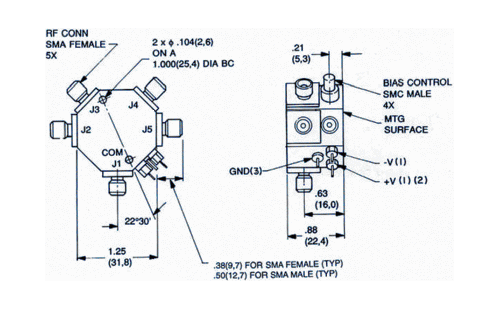
(1) Used only on units with integrated drivers
(2) +15V for G91/G92 Series
(3) Not used on driverless units except with option 33
Weight 2 oz. (57 grams) approx.
Dimensions in mm (Inches) Tolerances, unless otherwise indicated: .XX ±.02; .XXX ±.005