
Application Notes for RF Switches
SERIES 91 and 92
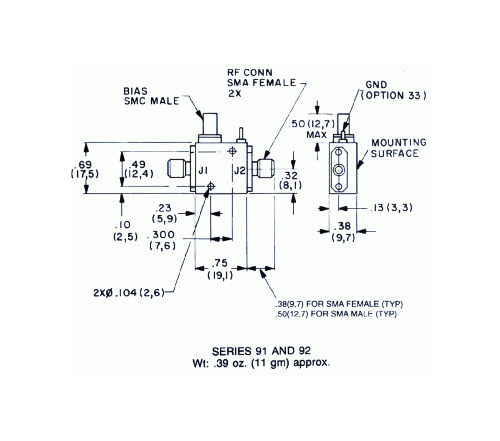
Series 91 and 92 switches provide high performance characteristics over a multi-octave range. Series 91 models cover the frequency range of 1 to 18 GHz, while Series 92 models cover the range from 0.2 to 4.0 GHz. These miniature switches measure only 0.75 x 0.69 x 0.38 inches.
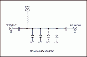
Both series use an integrated circuit assembly of up to four PIN diodes mounted in a microstrip transmission line. The circuit configuration is shown below.
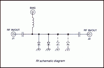
Application of a positive current to the bias terminal switches the unit OFF since the diodes are biased to a low resistance value. With zero or negative voltage at the bias terminal, the diodes are biased to high resistances and the unit is switched ON. Maximum rise and fall times are less than 10 ns.
SERIES F91 AND F92
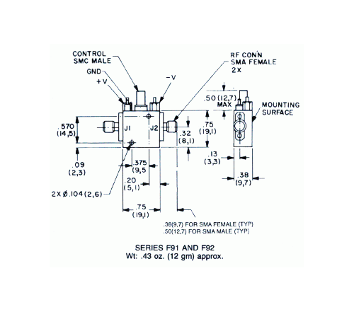
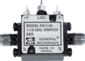
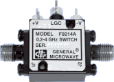
The Series F91 and F92 switches are the same as the corresponding Series 91 and 92 models except the units are equipped with integrated drivers, and the dimensions of the units are 0.75 x 0.75 x 0.38 inches. The proper current required to switch the unit ON or OFF is provided by the integral driver which requires +5 and -12 to -15 volt power supplies and is controlled by an external logic signal.
- Frequency range (Series 91): 1 to 18 GHz
- Frequency range (Series 92): 0.2 to 4 GHz
- Low VSWR and Insertion loss
- Up to 80 dB isolation
- Less than 10 ns rise and fall time
- Miniature size, light weight
UNITS With INTEGRATED DRIVERS
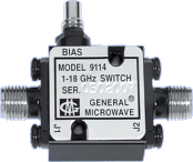
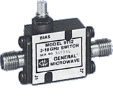
DRIVERLESS UNITS
PERFORMANCE CHARACTERISTICS
| FREQUENCY (GHz) | ||||||||
| MODEL NO.(1) | CHARACTERISTIC | 0.2 to 0.5 | 0.5 to 1.0 | 1.0 to 2.0 | 2.0 to 4.0 | 4.0 to 8.0 | 8.0 to 12.4 | 12.4 to 18.0 |
| 9112*, F9112A* |
Min. Isolation (dB) |
— — — |
— — — |
36 0.8 1.3 |
40 0.8 1.3 |
45 0.9 1.6 |
45 1.1 1.75 |
45 1.8 1.75 |
| 9114, F9114A |
Min. Isolation (dB) |
— — — |
— — — |
60 0.9 1.4 |
74 0.9 1.4 |
80 1.0 1.75 |
80 1.6 1.75 |
80 2.5 2.0 |
| 9214*, F9214A |
Min. Isolation (dB) |
40 1.0 1.5 |
45 1.0 1.5 |
50 1.0 1.5 |
50 1.0 1.5 |
— — — |
— — — |
— — — |
*Special-order product. Consult factory before ordering.
|
|
||||||||||||||||||||||||||||
| NOTES (1) Models prefixed with ‘F” are equipped with integrated TTL-compatible drivers; models without the ‘F” prefix are current-controlled units and are furnished without drivers. (2) For driverless units, shaped current pulses must be provided by the user. (3) 2W cw or peak with -20V back bias. (4) ON and OFF time and repetition rate specifications are only applicable to Series F91 and F92 units. |
|||||||||||||||||||||||||||||
|
|
||||||||||||||||||||||||||||||||||||||||||||
NOTES
(1) Not applicable to models 9214 & F9214. See Video Filter Options on Switches Applications Notes.
(2) Applicable only to 1 to 18 GHz switches. See impact of Option 55 on specifications
DIMENSIONS AND WEIGHTS