

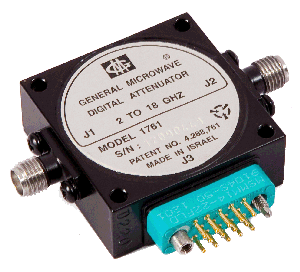
Application Notes for Microwave Attenuators
The D196 Series is a family of non-reflective voltage variable 60 dB PIN Diode Attenuators covering the frequency range from 0.5 GHz to 18 GHz in four overlapping multi-octave bands.
Each model in the Series is equipped with an integrated driver which controls the attenuation level at the rate of 10 dB/volt.
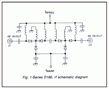
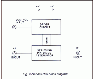
The RF circuit consists of two wide-band, T-pad attenuator sections connected in tandem. The driver circuit, which consists of a voltage-to-current converter and linearizing network, furnishes the proper series and shunt currents to control the attenuation value at the specified rate while simultaneously maintaining a bilateral match. (See figs. 1 and 2).
- Frequency range: 0.5 GHz-18 GHz in four overlapping bands
- Attenuation range: 60 dB
- Linear control: 10 dB/volt
- Low Insertion loss
- Non-reflective
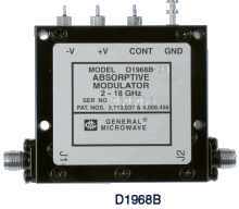
PERFORMANCE CHARACTERISTICS
| CHARACTERISTIC | MODEL D1960B* | MODEL D1961B | MODEL D1962B* | MODEL D1968B |
| Frequency Range (GHz) | 0.5-4 | 0.5-8 | 2-8 | 2-18 |
| Mean Attenuation Range (dB) | 60 | 60 | 60 | 60 |
| Insertion Loss (dB) (max) | 2.7 | 2.5 (0.5-4 GHZ) 3.2 (4-8 GHz) |
3.2 | 4.5 |
| VSWR (max) | 1.8 | 1.8 | 1.8 | 2.0 |
| Flatness up to 20 dB 40 dB 60 dB |
±0.5 dB ±0.75 dB ±1.0 dB |
±0.75 dB ±1.0 dB ±1.5 dB |
±0.75 dB ±1.0 dB ±1.5 dB |
±1.0 dB ±1.25 dB ±3.0 dB |
*Special-order product. Consult factory before ordering.
|
|
|||||||||||||||||||||||||||||||||
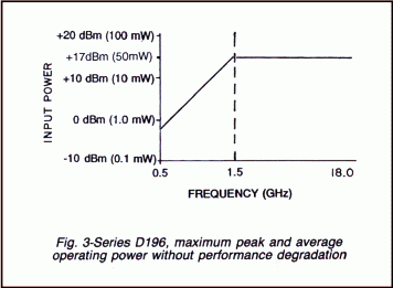
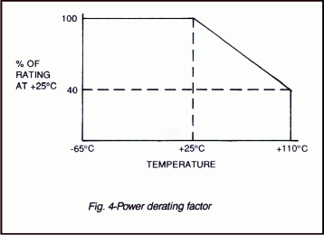
|
|
|||||||||||||||||||||||||||||||||
DIMENSIONS AND WEIGHT
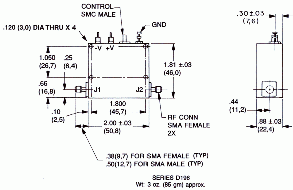
Dimensions are stated in
inches (mm). Tolerances, unless otherwise indicated: .XX ±.02; .XXX ±.008