

Application Notes for Microwave Attenuators
MODEL 1959
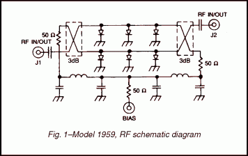
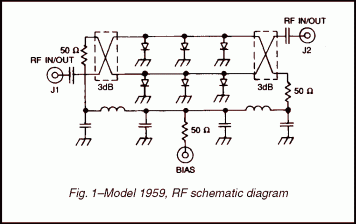
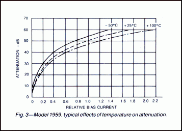
The Model 1959 is a current controlled attenuator/modulator that provides a minimum of 50 dB of attenuation over the frequency range of 18 to 40 GHz. As shown in figure 1 below, the RF circuit uses two shunt arrays of PIN diodes and two quadrature hybrid couplers. The quadrature hybrids are of a unique GMC microstrip design which are integrated with the diode arrays to yield a minimal package size.
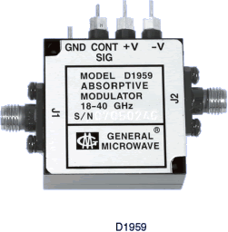
MODEL D1959
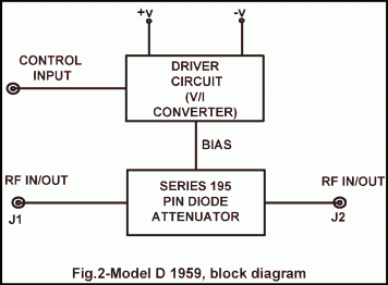
The Model D1959 voltage-controlled linearized attenuator/modulator is an integrated assembly of a Model 1959 and a hybridized driver circuit which provides a nominal transfer function of 10 dB per volt. (See figure 2 below.)
- Absorptive
- Current or voltage controlled
- 18 to 40 GHz frequency range
- High performance MIC quadrature hybrid design
- High speed
PERFORMANCE CHARACTERISTICS
| MODEL |
FREQUENCY RANGE (GHz) |
MAX. INSERTION LOSS (dB) |
MAX. VSWR |
FLATNESS (± dB) AT MEAN ATTENUATION LEVELS UP TO | |||
| 10 dB | 20 dB | 40 dB | 50 dB | ||||
| 1959 | 18-26.5 | 3.6 | 2.2 | 1.3 | 2.2 | 3.4 | 4.0 |
| 26.5-36 | 4.1 | ||||||
| 36-40 | 4.7 | ||||||
| D1959 | 18-26.5 | 4.1 | 2.2 | ||||
| 26.5-36 | 4.6 | ||||||
| 36-40 | 5.2 | ||||||
COMMON TO BOTH MODELS 1959 and D1959
|
|
|||||||||||||||||||||||||||||||||||||||||||||||||||||||||||||||||||||||||||
DIMENSIONS AND WEIGHT
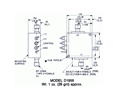
Dimensions are stated in inches (mm). Tolerances,
unless otherwise indicated: .XX ±.02; .XXX ±.008