

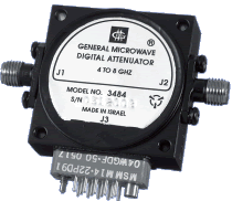
Application Notes for Microwave Attenuators
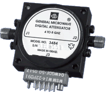
The Series 348 and 348H Digitally Programmable Attenuators provide greater than octave band performance in small hermetic packages ideally suitedfor high reliability applications. The Series 348 offers moderate power handling capability (100 mW) at switching speeds less than 500 ns while the 348H Series offers 200 ns switching speed at lower power Attenuation of all units is 60 dB with monotonic 0.25 dB step resolution.
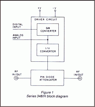
The attenuator is an integrated assembly of a sealed RF Microwave Integrated Circuit assembly and a sealed hybrid driver. Attenuation is controlled via a miniature 14 pin connector. See Fig. 1.
Although these units are primarily intended for use as digital attenuators, they can also be used as analog (voltage driven) attenuators or as combination analog/digital attenuators. (See note 4 below)
- 2 to 18 GHz
- Digital/Analog
- 8 Bit TTL
- Hermetically sealed
- Miniature
PERFORMANCE CHARACTERISTICS
| MODEL | FREQUENCY RANGE (GHz) | MAX. INSERTION LOSS (dB) | MAX. VSWR |
FLATNESS (± dB) AT MEAN ATTENUATION LEVELS UP TO |
||||
| 10 dB | 20 dB | 40 dB | 60 dB | |||||
| 3482/H* | 2.0 – 4.0 | 1.8 | 1.5 | 0.5 | 1.0 | 1.5 | 1.6 | |
| 1.5 – 4.5(1) | 1.9 | 2.0 | 0.7 | 1.6 | 3.0 | 3.5 | ||
| 3483*/H* | 2.6 – 5.2 | 2.0 | 1.6 | 0.5 | 1.0 | 1.5 | 1.6 | |
| 1.95 – 5.85(1) | 2.1 | 2.1 | 0.7 | 1.6 | 3.0 | 3.5 | ||
| 3484/H | 4.0 – 8.0 | 2.4 | 1.7 | 0.5 | 1.0 | 1.5 | 1.6 | |
| 3.0 – 9.0(1) | 2.5 | 2.2 | 0.7 | 1.6 | 3.0 | 3.5 | ||
| 3486/H | 6.0 – 12.0 | 2.7 | 1.8 | 0.7 | 1.0 | 1.5 | 1.6 | |
| 4.5 – 13.5(1) | 2.8 | 2.2 | 0.9 | 1.6 | 3.0 | 3.5 | ||
| 3488/H | 8.0 – 18.0 | 3.0(2) | 1.8(3) | 0.7 | 1.0 | 1.5 | 1.6 | |
| 6.0 – 18.0(1) | 3.0(2) | 1.8(3) | 0.9 | 1.6 | 3.0 | 3.5 | ||
* Special-order product. Consult factory before ordering.
(1) Specifications for the extended frequency ranges are typical.
(2) For 3488, 4.0 dB from 16-18 GHz. For 3488H, 3.5 dB from 12-16 GHz and 4.0 dB from 16-18 GHz.
(3) VSWR is 2.0 from 16-18 GHz.
|
|
|||||||||||||||||||||||||||||||||||||||||||||||||||||||||||||||||||||||||||||||||
DIMENSIONS AND WEIGHT
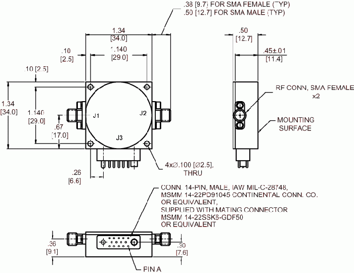
SERIES 348/H
wt: 2.4 oz. (68 gr) approx.
Dimensions are stated in inches (mm). Tolerances,
unless otherwise indicated: .XX ±.02; .XXX ±.008
| J3 POWER/LOGIC CONNECTIONS | |
| PIN |
FUNCTIONS (Note 1) |
| A | Digital/Power GND |
| B | Logic Control (Note 2) |
| C | –12 to –15V |
| D | 0.25 dB (LSB) |
| E | 0.5 dB |
| F | 1 dB |
| H | 4 dB |
| J | 2 dB |
| K | 16 dB |
| L | 32 dB (MSB) |
| M | +12 to +15V |
| N | 8 dB |
| P | GND |
| R | Analog Input (Notes 3&4) |
NOTES
(1) All unused logic inputs must be grounded.
(2) For normal TTL programming control, PIN B must be grounded or at Logic 0. Application of Logic 1 to PIN B overrides the digital input and sets the unit to insertion loss. To interface with other logic families (e.g., CMOS, MTL, NMOS, etc.) contact factory.
(3) If Analog input is not to be used, then connect PIN R to PIN P.
(4) To use the unit as a voltage controlled attenuator, apply a control voltage of 0 to +6V at PIN R. The slope of attenuation will be nominally 10 dB/V. For a non-zero source resistance (RO) of up to 500 ohms, the attenuation error is approximately –.0017 • RO • VIN dB and the slope will decrease by approximately 0.17 dB/V per 100 ohms of source resistance.
Using the 348/H Series attenuator as both a digital and analog control attenuator, the total attenuation ATT = 10 • VIN + programmed digital attenuation. The maximum attainable mean attenuation is 60 dB.