

Application Notes for RF Switches
Reflective SP2T SWITCHES
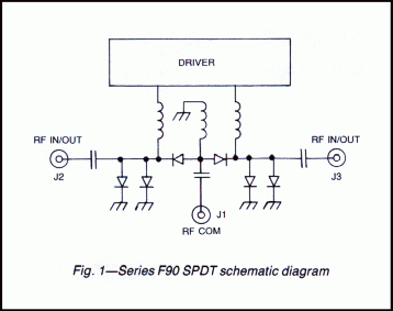
Series F90 SP2T switches use an integrated assembly of PIN diodes mounted in a microstrip transmission line in a series-shunt arrangement as shown in Figure 1.
When applying positive current (by the driver), the associated port is OFF since the corresponding shunt diodes are biased to a low resistance and the series diode to a high resistance. With negative current at the bias terminal converse conditions are established and the port is ON. All models are supplied with integrated drivers. Standard units are supplied with logic that turns a port ON with the application of a logic “0” control signal. Maximum rise and fall times are less than 10 ns.

- 18 to 40 GHz frequency range
- Rise and fall times less than 10 ns
- Low VSWR and Insertion loss
- Up to 65 dB isolation
PERFORMANCE CHARACTERISTICS
| FREQUENCY (GHz) | |||
|---|---|---|---|
| MODEL NO. | CHARACTERISTIC | 18-26.5 | 26.5-40 |
| F9021 | Min. Isolation (dB) |
30
|
20
|
| Max. Insertion Loss (dB) |
3.0
|
3.6
|
|
| Max. VSWR (ON) |
2.1
|
2.3
|
|
| F9022 | Min. Isolation (dB) |
45
|
40
|
| Max. Insertion Loss (dB) |
3.2
|
4.0
|
|
| Max. VSWR (ON) |
2.2
|
2.3
|
|
| F9023 | Min. Isolation (dB) |
65
|
55
|
| Max. Insertion Loss (dB) |
3.5
|
4.5
|
|
| Max. VSWR (ON) |
2.3
|
2.5
|
|
SWITCHING CHARACTERISTICS |
|||||||||||||||||||||||||||||||||||||||||||||
|---|---|---|---|---|---|---|---|---|---|---|---|---|---|---|---|---|---|---|---|---|---|---|---|---|---|---|---|---|---|---|---|---|---|---|---|---|---|---|---|---|---|---|---|---|---|
| 10 ns max. | |||||||||||||||||||||||||||||||||||||||||||||
| 25 ns max. | |||||||||||||||||||||||||||||||||||||||||||||
| 20 MHz max. | |||||||||||||||||||||||||||||||||||||||||||||
Power Handling Capability |
|||||||||||||||||||||||||||||||||||||||||||||
| 1W cw or peak | |||||||||||||||||||||||||||||||||||||||||||||
| 1W average, 75W peak (1µsec max. pulse width) | |||||||||||||||||||||||||||||||||||||||||||||
| +5V ±2%, 75 mA -12 to -15V, 50 mA |
|||||||||||||||||||||||||||||||||||||||||||||
CONTROL CHARACTERISTICS |
|||||||||||||||||||||||||||||||||||||||||||||
| TTL, advanced Schottky, one unit load. (A unit load is 0.6 mA sink current and 20 µA source current.) | |||||||||||||||||||||||||||||||||||||||||||||
| Logic “0” (–0.3 to +0.8V) for switch ON and Logic “1” (+2.0 to +5.0V) for switch OFF. | |||||||||||||||||||||||||||||||||||||||||||||
|
|||||||||||||||||||||||||||||||||||||||||||||
DIMENSIONS AND WEIGHT
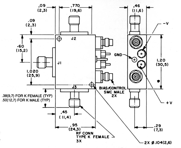
Dimensions in mm (Inches) Tolerances, unless otherwise indicated: .XX ±.02; .XXX ±.005