

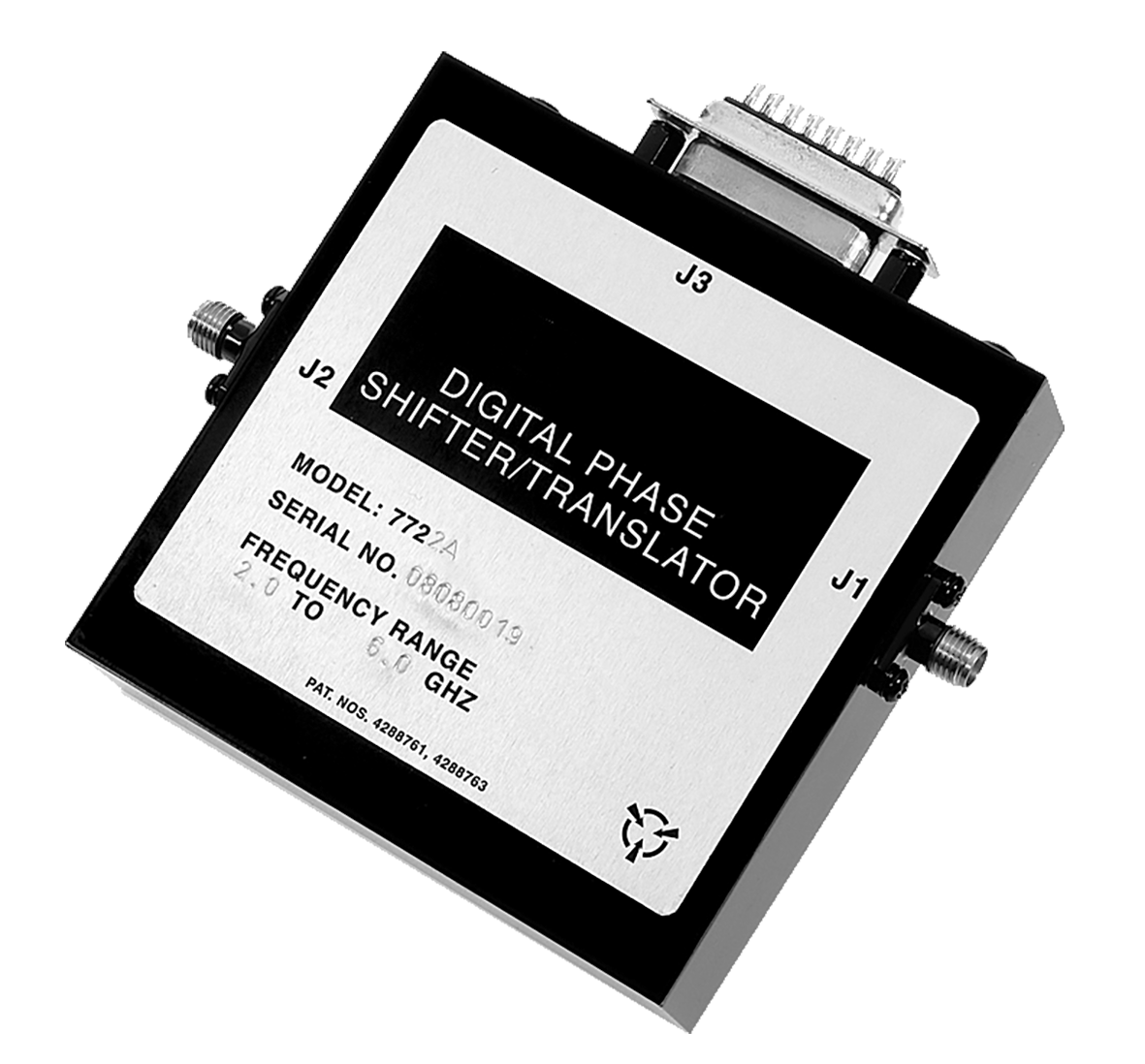
Application Notes for Microwave Phase Shifter
DIGITAL PHASE SHIFTER & ANALOG PHASE SHIFTER
Both Series, 77 and 78, comprise a family of eight solid-state PIN diode phase shifters covering the frequency range from 0.5 to 18 GHz in four bands: 0.5 to 2 GHz, 2 to 6 GHz, 4 to 12 GHz and 6 to 18 GHz. All models provide a full 360° range of phase shift and may also be used for frequency translation applications.
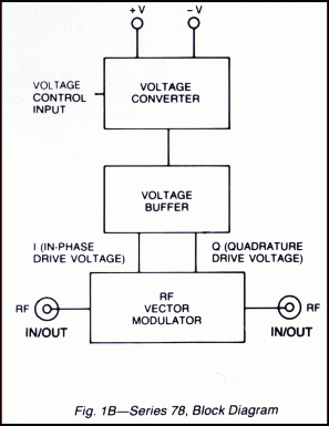
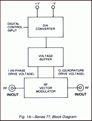
Each unit is an integrated assembly of an RF vector modulator and a driver circuit, consisting of a 10-bit D/A converter and a voltage buffer in the Series 77 digital units (see Fig. 1A) and a voltage converter and buffer in the Series 78 analog configuration (see Fig. 1 B).
The phase in the Series 77 is digitally controlled over a full 360° in 0.35° discrete steps. The voltage converter in the Series 78 consists of a 8 bit A/D converter followed by D/A converter, and converts a continuous analog input voltage into discrete steps of 1.41°.
5 to 18 GHz in four bands
- 0.5 to 2 GHz
- 2 to 6 GHz
- 4 to 12 GHz
- 6 to 18 GHz
10 Bit digitally programmable (Series 77)
Analog control (Series 78)
High speed
Guaranteed monotonicity
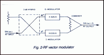
Phase shift is achieved utilizing the RF vector modulator approach shown in Fig. 2. The 3 dB hybrid coupler divides the RF signal into two quadrature components which are then modulated in proportion to the sine and cosine of the desired phase shift. The signals are then combined in-phase to yield the phase-shifted output.
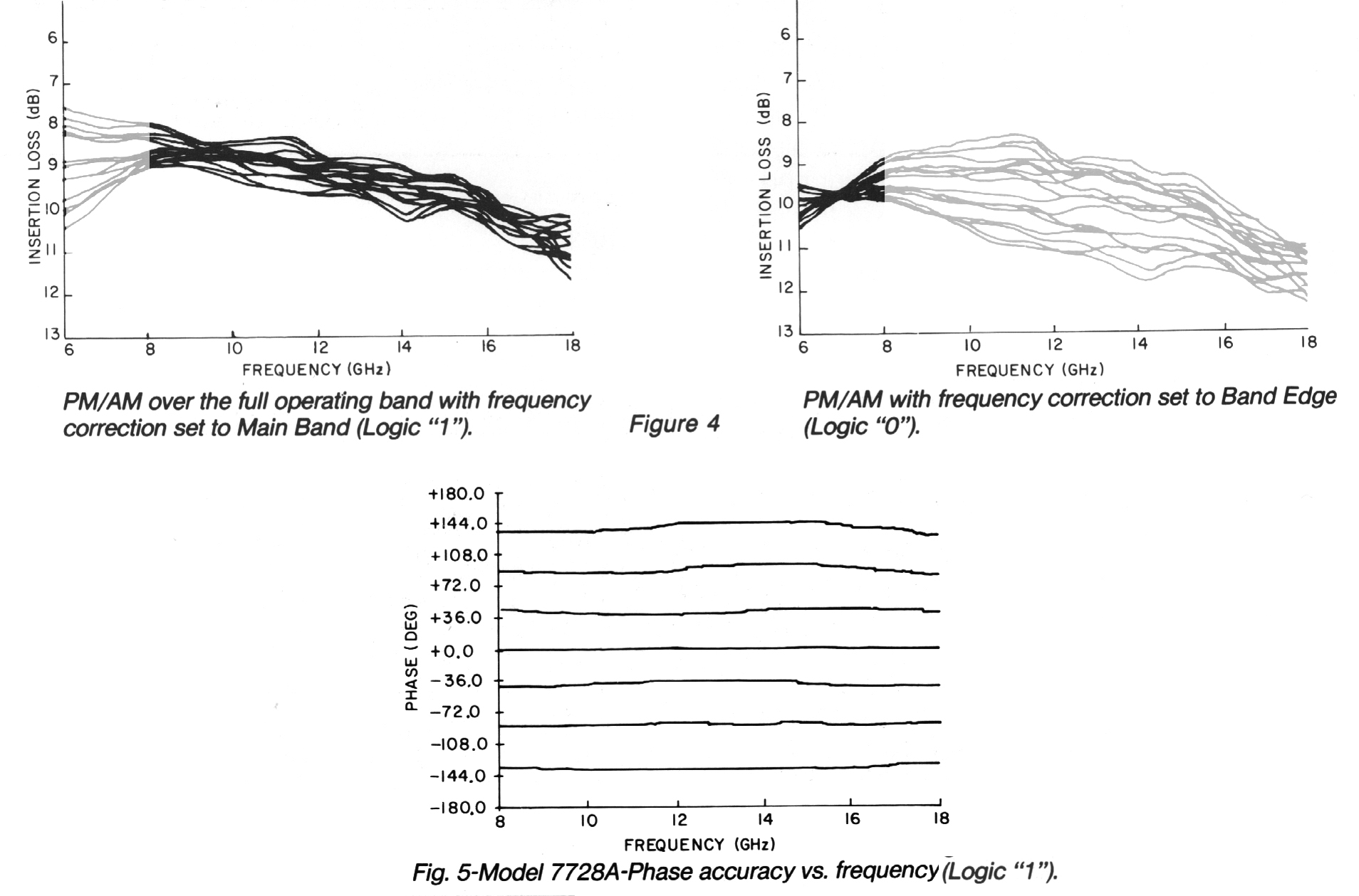
Special attention in the design of the units has been paid to those characteristics which affect their performance as frequency translators. These include minimizing PM-to-AM conversion, use of high slew rate drivers, and optimizing phase shift linearity with applied signal. As a result, carrier and sideband suppression levels of over 25 and 20 dB, respectively, are obtained in the main bands. The same carrier and sideband performance can be realized over the full stretch band when the internal frequency correction circuit is employed.
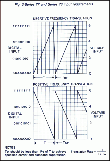
See Fig. 3 for input voltage control requirements for Series 77 and 78 when used as a frequency translator.
On special order, frequency translators can be provided for operation over reduced bandwidths with suppression levels of up to 35 dB. Consult the factory for special requirements
PERFORMANCE CHARACTERISTICS
| Control | -10 bit TTL |
| Nominal Resolution | 0.35o |
| Logic Input | |
| Logic “0” (Bit OFF) | -0.3 to +0.8V @ 500 µA max |
| Logic “1” (Bit ON) | +2.0 to +5.0V @ 100 µA max |
| Control Voltage | 0 to +6V |
| Sensitivity | 23.4 mV/LSB |
| Resolution | 1.41° |
| Step Uncertainty | 0.7° max, 0.3°typ. |
| Input Resistance | 2K ohms |
| Power Handling Capability Without Performance Degradation | +20 dBm (+7 dBm for 7720A, 7820) |
| Survival | +30 dBm |
| Harmonics | 30 dBc |
| Phase Variation | 0.1°/°C |
| VOLTAGE | SERIES 77 | SERIES 78 |
| +5V to +5.5V | 100 mA | 200 mA |
| +12 to +15V | 100 mA | 100 mA |
| -12 to -15V | 90 mA | 90 mA |
RECOMMENDED SEQUENCE OF POWERING THE SUPPLIES
| 1. | Set command lines to logic level “0”. |
| 2. | Turn on the -12 to -15V power supply. |
| 3. | Turn on the +12 to +15V power supply. |
| 4. | Turn on the +5V power supply. |
| 5. | Set command lines to logic level “1”. |
| 6. | Now you can start to work (if you want for example zero phase, set again all control lines to “0”) |
| MODEL NOS. | FREQUENCY RANGE (GHz) | INSERTION LOSS (Max.) | VSWR (Max.) | ACCURACY(1) (Max.) | PM/AM (Max.) |
| 7720A & 7820 | Main Band 0.7-1.9(1) | 11.5 dB | 1.75 | ±10° | ±1.1dB |
| Stretch Band 0.5-2.0(2) | 13.0 dB | ±15° | ±2.5dB | ||
| Band Edges 0.5-0.7 & 1.9-2.0(3) | 13.0 dB | ±10° | ±1.1dB | ||
| 7722A & 7822 | Main Band 2.6-5.2(1) | 10.0 dB | 1.6 | ±10° | ±1.1dB |
| Stretch Band 2.0-6.0(2) | 11.0 dB | ±15° | ±1.5dB | ||
| Band Edges 2.0-2.6 & 5.2-6.0(3) | 11.0 dB | ±10° | ±1.1dB | ||
| 7724A & 7824 | Main Band 4.5-10.5(1) | 10.5 dB | 1.8 | ±10° | ±1.1dB |
| Stretch Band 4.0-12.0(2) | 12.0 dB | ±15° | ±2.0dB | ||
| Band Edges 4.0-4.5 & 10.5-12.0(3) | 12.0 dB | ±10° | ±1.1dB | ||
| 7728A & 7828 | Main Band 8.0-18.0(1) | 12.0 dB | 2.0 | ±12° | ±1.25dB |
| Stretch Band 6.0-18.0(2) | ±15° | ±2.0dB | |||
| Band Edges 6.0-8.0(3) | ±12° | ±1.25dB | |||
|
OTHER SPECIFICATIONS
Switching Speed (50% TTL to within 10° of Final Phase Value): 500 ns Max. |
|||||
| TRANSLATION RATE (min.) | CARRIER (1) SUPRESSION (min.) | SIDE BAND (1) SUPRESSION (Min) | INTERATION LOSS VARIATION (Max.) with translation rate: |
| 0 to 50 kHz(4) | Main Band: 25dB Stretch Band: 18dB |
Main Band: 20dB Stretch Band: 15 dB |
50kHz: 1dB |
| >50 to 500 kHz(4) | Main Band: 20dB Stretch Band: 15dB |
Main Band: 18 dB Stretch Band: 12 dB |
200kHz: 1dB 500kHz: 3dB |
- For Main Band optimized operation, apply logic HIGH to pin 3 or leave it floating.
- For Stretch Band operation, apply logic HIGH to pin 3 or leave it floating. While performance is optimized over the Main Band, the reduced performance as stated in Stretch Band specifications apply to band edges.
- For Band Edges optimized operation, apply logic LOW to pin 3.
- All specifications are met using five most significant bits for 0 to 50 kHz translation rates. For 50-500 kHz translation rates, only the four most significant bits are used.
In addition to the standard wide band Phase Shifters, KRATOS General Microwave is offering Narrow Band Phase Shifters. These units are available both as standard catalog units and as customized units meeting specific customer’s requirements. The narrow band units have better performances and lower prices.
| Frequency Range | Model Number | Phase Accuracy | PM/AM | Insertion Loss |
| 8.0 to 12.4 GHz | 7728-NB-0812 | ± 8o (max.) | ± 0.75 dB | 12.0 dB (max.) |
| 12.0 to 14.5 GHz | 7728-NB-1214 | ± 8o (max.) | ± 0.75 dB | 12.0 dB (max.) |
| Operating Temperature Range | -54° to + 100°C |
| Non-Operating Temperature Range | -65° to + 125° C |
| Humidity | MIL-STD-202F, Method 103B, Cond. B (96 hrs at 95%) |
| Shock | MIL-STD-202F, Method 213B, Cond. B (75 G, 6 msec) |
| Vibration | MIL-STD-202F, Method 204D, Cond. B (.06″ double amplitude or 15G, whichever is less) |
| Altitude | MIL-STD-202F, Method 105C Cond. B (50,000 ft.) |
| Temp. Cycling | MIL-STD-202F, Method 107D Cond. A, 5 cycles |
Mating power/control connector
| Option no. | Description |
| 7 | Two SMA male rf connectors |
| 10 | One SMA male (J2) and one SMA female (J1) rf connector |
| G09 | Guaranteed to meet Environmental Ratings |
| G12 | RoHS Compliant |
| G18 | REACH Compliant |
| PIN No. | FUNCTION | |
| SERIES 77 (1) | SERIES 78 | |
| 1 | -12 V to -15 V | -12 V to -15 V |
| 2 | +12 V to +15 V | +12 V to +15 V |
| 3 | Freq.Correction Circuit Select(3) “0” = Band Edge | Freq.Correction Circuit Select “0” = BandEdge |
| 4 | 1.4°(3) | Not Used |
| 5 | 5.6°(3) | Not Used |
| 6 | 45.0°(3) | Not Used |
| 7 | 180.0° (MSB)(3) | Not Used |
| 8 | 90.0°(3) | Not Used |
| 9 | Ground | Ground (Sig) |
| 10 | 0.7°(3) | Ground (Pwr) |
| 11 | 22.5° | Not Used |
| 12 | 2.8° | Not Used |
| 13 | 11.3° | Not Used |
| 14 | 0.35° (LSB) | Control Voltage |
| 15 | +5V to +5.5V DC | +5V to +5.5V DC |
- Unused logic bit must be grounded.
- Must not exceed +7VDC See footnote(3) below.
- Must not be greater than +0.3VDC above voltage at pin 15.
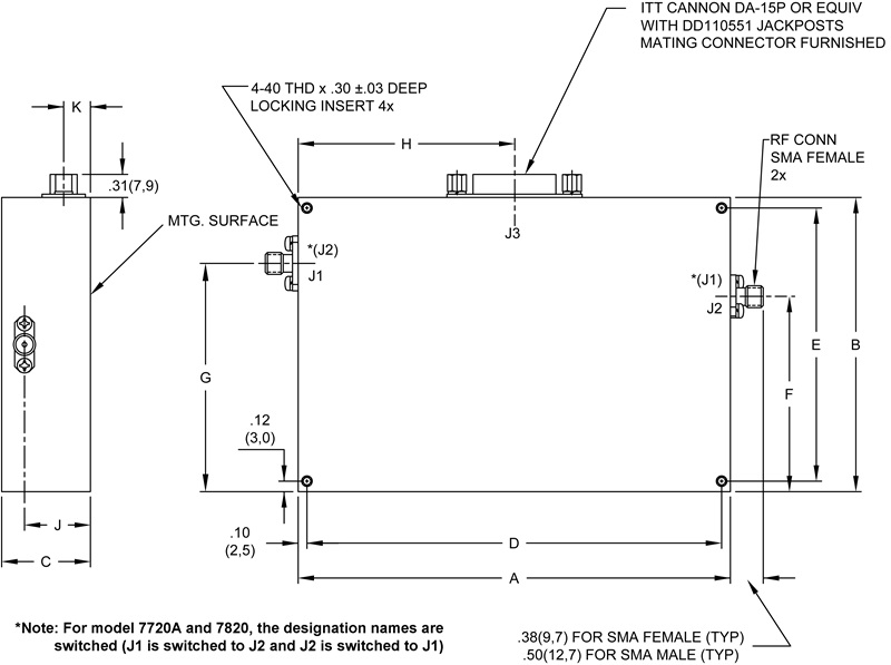
OUT LINE DRAWING
| MODEL | A | B | C | D | E | F | G | H | J | K | WEIGHT(APPROX) |
| 7720A | 4.95 ± .03(125,7) | 3.38 ±.03(85,9) | 1.02(25,9) | 4.75 ±.01(120,7) | 3.12 ± .01(79,2) | 2.62(66,5) | 1.69(42,9) | 2.48(62,9) | .73(18,5) | 32(8,1) | 13 oz. (369 gm) |
| 7820 | 1.48 (37,6) | 1.18 (30,0) | .78(19,8) | 15 oz. (425 gm) |
|||||||
| 7722A | 3.25 ± .03(82,6) | 3.25 ± .03(82,6) | .84(21.3) | 3.05 ± .01(77,5) | 3.00 ± .01(76,2) | 1.63(41,4) | 1.99(50,5) | 1.63(41,4) | .66(16,8) | .32(8,1) | 9 oz. (255 gm) |
| 7822 | 1.25(31,8) | 1.07(27,2) | .72(18,3) | 10 oz. (284 gm) |
|||||||
| 7724A | .84(21.3) | 1.83(46,5) | .66(16,8) | .32(8,1) | 9 oz. (255 gm) |
||||||
| 7824 | 1.25(31,8) | 1.07(27,2) | .72(18,3) | 10 oz. (284 gm) |
|||||||
| 7728A | 2.50 ± .03(63,5) | 3.00 ±.03(76,2) | .88(22,4) | 2.30 ±.01(58,4) | 2.75 ±0.1(69,9) | 1.50(38,1) | 1.63(41,4) | 1.25(31,8) | .71(18,0) | .39(9,9) | 6 oz. (170 gm) |
| 7878 | 1.19(30,2) | 1.02(25,9) | .69(17,6) | 8 oz. (227 gm) |
|||||||
|
Dimensions are stated in inches (mm). Tolerances, |
|||||||||||