

Application Notes for: Microwave Phase Shifters, IQ Vector Modulators & Frequency Translators
The Model F1938 is a high-speed 0° or 180° phase shifter that operates over the 6 to 18 GHz frequency range. It features a double-balanced design that provides excellent phase accuracy over its entire frequency range. The rf design is shown below. The currents required to switch the unit between states are provided by the integrated driver, which is controlled by an external logic signal.
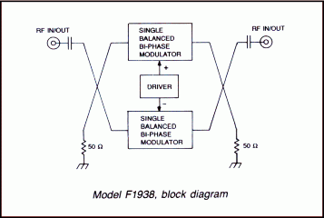
- Frequency range: 6-18 GHz
- Different phase shift: 180°±10°
- High speed: 5 ns (10-90% RF)
- Low VSWR and Insertion loss
- Small size, light weight
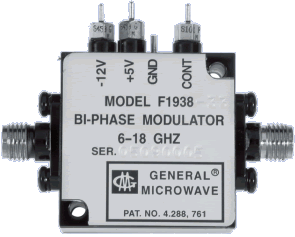
PERFORMANCE CHARACTERISTICS
| Frequency Range | 6 to 18 GHz |
| Differential Phase Shift(1) | 180o ±10o |
| Switching Characteristics (2) | |
| ON Time | 20 ns. Max. |
| OFF Time | 20 ns. Max. |
| Rise Time | 5 ns. Max. |
| Fall Time | 5 ns. Max. |
| Insertion Loss (1) | >6 to 16 GHz, 3 dB max. >16 to 18 GHz, 3.5 dB max. |
| VSWR (1) | 2.0 max. |
| Change of Insertion Loss With Phase Shift | 1.0 dB max. |
| Carrier Suppression | 20 dB min. |
| Modulation Rate | 10 MHz max. |
| Power Handling Capability | |
| Without Performance Degradation | 1W cw or peak |
| Survival Power | 2W average, 25W peak (1 µsec max. pulse width) |
| Power Supply Requirements | +5V ±5%, 65 mA -12V to -15V, 20 mA |
CONTROL CHARACTERSTICS
| Control Input Impedance | Schottky TTL, two-unit load. (A unit load is 2 mA sink current and 50 µA source current.) |
| Control Logic | Alternate applications of logic “0” (-0.3 to +0.8V) and logic “1” (+2.0 to +5.0V) switches phases by 180o |
NOTES:
- With option 85, within Frequency Band of 16 to 18 GHz will be:
- Insertion Loss: 4 dB max
- Differential Phase Shift: 180o ±15o
- VSWR: 2.2:1 max.
- As measured with a phase bridge.
OPTION (G09) ENVIRONMENTAL RATINGS
| Operating Temperature Range | -55°C to + 110°C |
| Non-Operating Temperature Range | -65°C to + 125°C |
| Humidity | MIL-STD-202F, Method 103B, Cond. B (96 hrs. at 95%) |
| Shock | MIL-STD-202F, Method 213B, Cond. B (75G, 6 msec) |
| Vibration | MIL-STD-202F, Method 204D, Cond. B (.06″ double amplitude or 15G, whichever is less) |
| Altitude | MIL-STD-202F, Method 105C, Cond. B (50,000 ft.) |
| Temp. Cycling | MIL-STD-202F, Method 107D, Cond. A, 5 cycles |
AVAILABLE OPTIONS
| Option No. | Description |
| 3 | SMA female control connector |
| 7 | Two SMA male RF connectors |
| 10 | One SMA (J1) male and one SMA female (J2) RF connector |
| 33 | EMI filter solder-type control terminal |
| 85 | SMA RF connectors (see note (1) above for specification change with this option). |
| G09 | Guaranteed to meet Environmental Ratings |
| G12 | RoHS Compliant |
| G18 | RREAC Compliant |
DIMENSIONS AND WEIGHT
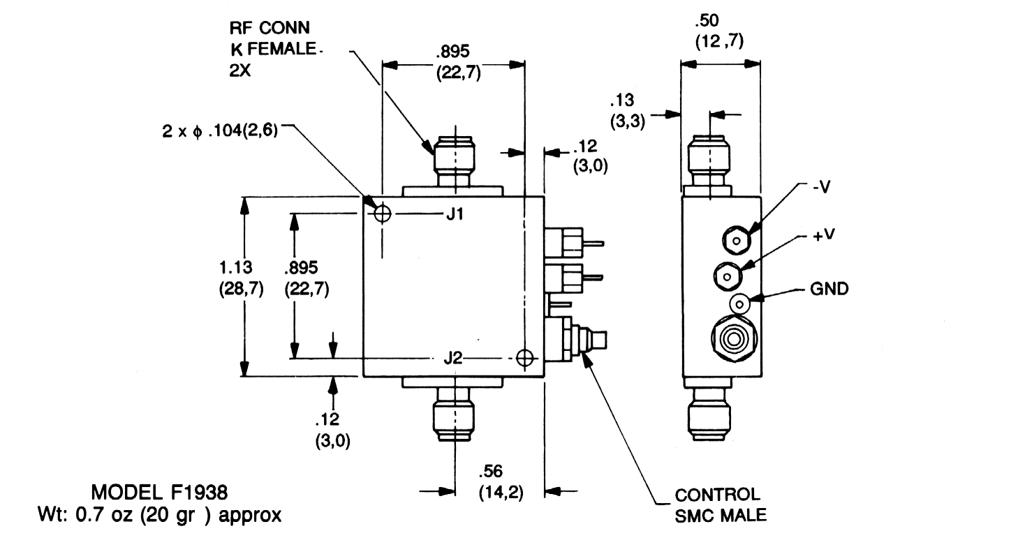
Dimensions are stated in inches (mm). Tolerances, unless otherwise indicated: .XX ±.02; .XXX ±.008